Open Science Repository Engineering
doi: 10.7392/Engineering.70081934
LCL Filter for 3-Ø Stable Inverter Using Active Damping Method (Genetic Algorithm)
Rajendra Aparnathi [1], Ved Vyas Dwivedi [2]
[1] Faculty of Technology and Engineering, Maharaja Sayajirao University of Baroda, Gujarat, India
[2] Noble Group of Institutions, Junagadh, Gujarat, India
Abstract
The use of an LCL-filter mitigates the switching ripple injected in the grid by a three-phase active rectifier or three-phase voltage source inverter. However stability problems arise in the current control loop. In order to overcome them a damping resistor can be inserted, at the cost of efficiency. On the contrary, the use of the active damping seems really attractive but it is often limited by the use of more sensors with respect to the standard control and by the complex tuning procedure. This research paper introduces a novel active damping method that does not need the use of more sensors and that can be tuned using Genetic Algorithms (GA) for optimized performance. It consists of adding a filter on the reference voltage for the converter/inverter modulator. The tuning process of this filter is easily done, for a wide range of sampling frequencies using GAs.
Keywords: LCL filter, direct power control (DPC), voltage source inverter (VSI), voltage oriented control (VOC), pulse with modulation (PWM).
Citation: Aparnathi, R., & Dwivedi, V. V. (2013). LCL Filter for 3-Ø Stable Inverter Using Active Damping Method. Open Science Repository Engineering, Online(open-access), e70081934. doi:10.7392/Engineering.70081934
Received: January 24, 2013
Published: February 28, 2013
Copyright: © 2013 Aparnathi, R., & Dwivedi, V. V. Creative Commons Attribution 3.0 Unported License.
Contact: [email protected]
1. Introduction
The front-end stage of a power converter is not a mass produced product. In fact, it should be specifically designed for the application it is used for, such as chemical, electrolysis, aluminium, graphitizing furnace, zinc electrolysis, copper refining, traction substation, AC and DC drive system. If the attention is focused to applications that can take advantage from dc voltage regulation, the diode bridge with on-load tap changers or with saturable core reactors and the thyristor-bridge are still the preferred design solutions in respect to diode-bridge plus chopper systems [1]. For historical reasons, the diode-bridge plus chopper have been considered as the “new” solution in the rectifier field. In fact the chopper has been successfully experimented in traction system over the past three decades. Hence, it was quite natural to consider the chopper as the next step also for other rectifier applications. However, the use of a chopper stage increases the number of switching devices, which results in a higher failure rate and mean time to repair [1 - 2].In this scenario, active rectifiers, employing the VSIs are valid competitors both for traditional solutions, such as thyristor, and for newer ones, as chopper, due to the reduced number of power devices and the enhanced capability of grid current and power factor control. Particularly VSIs, employing PWM techniques, are the widest used power converters for applications such as industrial motor drives, robotics, air conditioning and ventilation, uninterruptible power supplies and electric vehicles [2],[3]. Thus they are considered as prime candidates for interfacing high-power electronic equipment to power supply lines.
Over the last few years an interesting emerging control technique, the direct power control (DPC), has been developed analogously with the well-known direct torque control used for adjustable speed drives. In DPCs, there are no internal current loops [3]. PWM modulator blocks, because of the converter/inverter switching states, are appropriately selected by a switching table based on the instantaneous errors between the commanded and estimated values of active and reactive power. The principal drawbacks are the need for a high sampling frequency required to obtain satisfactory performance and the variable switching frequency. However, this can be solved by the combination of a modulator and the DPC-technique [4],[5],[6].
Adjustable speed drives in hoisting applications (cranes and elevators), in high inertia applications (centrifuges) and in the end stage of wind turbines have highly demanding safety issues but cannot adopt high inductance values. Thus the use of an LCL-filter on the ac side is an interesting solution: reduced values of the inductance can be used and the grid current is almost ripple free. In this way, a low THD of the current is obtained. The design of the LCL-filter has already been investigated. Attention has also been paid to the possible instability of the system caused by the zero impedance that the LCL-filter offers at its resonance frequency [7 - 10]. Some passive damping solutions of the filter have already been studied, tested and industrially used in the switching converter field.
The use of a damping resistor increases the encumbrances, the losses could result in need for more cooling (e.g., forced) and efficiency decrease becomes a key point. Thus, it seems very attractive to use an active damping method by means of control in order to avoid system instability without increasing the losses. This solution has already been partially studied. A proposal is made to add a derivative action based on the line side current in the current control loop; thus new sensors are needed. The LCL-filter capacitor voltage is controlled with a lead-lag network; the tuning of the network is described. Moreover an interesting approach to perform active damping is proposed: a virtual resistor is added. The virtual resistor is an additional control algorithm that makes the filter behaves as if it had a real resistor connected to it. This approach is attractive because it can be related to a “real” physical component. In this case, an additional current sensor is needed if the virtual resistor is connected in series to the filter inductor or capacitor and an additional voltage sensor is needed if it is connected in parallel [11], [12].
All the previous active damping methods require additional sensors and they do not mention the influence of the damping on the dynamics and on the susceptibility of the system. In this paper a new damping method is introduced. It does not need the use of additional sensors and the tuning can be done with the help of genetic algorithms. Soft computing, such as genetic algorithm, has been successfully applied both to drive control and to the design of a single-phase rectifier system. Genetic algorithms are used to optimize the poles. Placement of an observer using a cost function that takes into account the system dynamics. A single-ended boost PFC converter is optimized to fulfill the PFC and EMI standards. In short, the genetic algorithms have been considered particularly suitable to optimize nonlinear trade-off problems involving multiple parameters. The proposed active damping is based on the use of a filter on the reference voltage for the modulator. The tuning process of this filter is easily done, for a wide range of sampling frequencies, with the use of genetic algorithms. This method is used only for the optimum choice of the parameters of the filter and an on-line implementation is not needed [11].
The analysis is validated with three design cases characterized by different requirements in terms of stability and dynamic performance. Section II of this paper describes the modeling of an LCL filter based active rectifier, while the controller modeling is explained in section III. The current control loop analysis has been presented in section IV, and section V discusses about the active damping methods. The stability analysis is highlighted in the section VI of this paper which leads to discussions on the results followed by a good potential references.
2. Modelling the LCL filter based active rectifier
The LCL-filter based VSI active rectifier is modelled in [6] is reproduced here in Fig. 1:![Fig. 1: Three-phase LCL-filter based active rectifier [6]](images/70081934fig1e.jpg "Fig. 1: Three-phase LCL-filter based active rectifier [6]")
Fig. 1: Three-phase LCL-filter based active rectifier [6]
The differential equations for the LCL-filter in the stationary reference frame are expressed in (1)-(3).
For rotating frame, the (1)-(3) can be rearranged as in (4)-(9) in the dq-frame.
(8)
Where ia1, ib1, ic1 are grid currents; and ia2, ib2, ic2 are inverter/converter currents; io is total o/p current; iC is the o/p current passing through the o/p balancing capacitor(C) being used as a filter; iL is the o/p load current. ea,eb,ec are grid voltages; Vc is the voltage observed at filter capacitor (Cf); Va,Vb,Vc are i/p inverter voltages; Vo is o/p voltage. R1-L1 is grid inductance while R2-L2 is inverter/converter inductance; and S represents the inverter/converter switches.
Also in this case, the (4)-(9) show how both the currents and the capacitor voltages are dependent on the cross-coupling terms ωid(t) and ωiq(t).
3. Controller
Low and high frequency models, as well as the use of coordinate transformation and small-signal linearization for control purposes, are needed in order to design the basic controls such as phase control and current control of the active rectifier [9-10].A. AC current controller
The entire ac current control (CC) is more suitable because the current controlled converter exhibits, in general, better safety, better stability and faster response. This solution ensures several additional advantages. The feedback loop also results in some limitations, such as that fast-response voltage modulation techniques must be employed, like PWM. Optimal techniques, which use pre calculated switching patterns within the ac period, cannot be used, as they are not oriented to ensure current waveform control [1],[7],[9], [13].The CC has been applied to active rectifier in order to ensure dc-link voltage regulation. The current controlled rectifier has been applied to front-end operation in ac drives with dc-link voltage regulation. The use of an LCL-filter claims for a deep dynamic and stability analysis of the current control loop [11], [14].
B. Two axis-based current control
The most used control technique is the two axis-based Voltage Oriented Control (VOC) as shown in fig 2. Rectifier is based on the use of a rotating dq-frame oriented technique such as the d-axis is aligned on the grid voltage vector.
The space-vector of the fundamental has constant components in the dq-frame while the other harmonic’s space vectors have pulsating components. The main purpose of the active rectifier is to generate or to absorb sinusoidal currents. The components of the reference current in the dq-frame are dc quantities. The reference current d-component (i*d) is controlled to perform the dc voltage regulation, while the reference current q-component (i*q) is controlled to obtain a unity power factor. To have the grid current vector in phase with the grid voltage vector, i*q should be zero. The dc-link voltage control is achieved through the control of the power exchanged by the converter. The dc-link voltage loop is the outer loop and the current loops are the inner loops. These internal loops are designed to achieve short settling times and unity gain. On the other hand, the main goals of the outer loop are optimum regulation and stability, thus the voltage loop could be designed to be 5-29 times slower [8].
Therefore, the internal and the external loops can be considered decoupled, and there by the actual grid current components can be considered equal to their references when designing the outer dc-link controller [15].However some instability in the dc-loop can arise when the rectifier is working in the re-generative operation. This kind of approach can be easily used to design more advanced control methods such as Lyapunov-based and sliding mode controllers have been adopted aiming to system stability and the absence of steady state errors respectively.

Fig. 2: Voltage Oriented Control based on the use of a rotating
C. Emerging control techniques
No amongst the different emerging control techniques the Direct Power Control (DPC) is gaining interest for its simple implementation while Fuzzy Logic and Genetic Algorithm for their capability to optimize the system performance, if current sensors are not adopted, or if active damping has to be implemented [8], [14].
Level-1 Direct power control: A level-1 in the last years the most interesting emerging technique has been the direct power control developed in analogy to the well-known direct torque control used for drives. In DPC there are no internal current loops and no PWM modulator block because the converter switching states are appropriately selected by a switching table based on the instantaneous errors between the commanded and estimated values of active and reactive power shown in Fig 6. The main advantage of the DPC is in its simple algorithm instead the main disadvantage is in the need for high sampling frequency required to obtain satisfactory performances [1], [3].

Fig. 3: DPC based on the active and reactive power calculation
Level-2 Genetic algorithm: A level-2Soft computing, such as genetic algorithm, can be used to optimise the design of rectifier systems [11], [18] or to adapt the parameters of advanced controls such as active damping. Particularly introduces a new active damping method that does not need the use of more sensors and that can be tuned using genetic algorithms. It consists of adding a filter on the reference voltage for the converter’s modulator. The tuning process of this filter is easily done, for a wide range of sampling frequencies, with the use of genetic algorithms. This method is used only for the optimum choice of the parameters of the filter and an on-line implementation is not needed. Thus the resulting active damping solution does not need new sensors or complex calculations [11]
4. Current loop analysis
The AC current control (CC) is considered particularly suitable for active rectifiers due to its safety, stability performance and fast response. Usually the CC is implemented in a dq-rotating frame that has the d-axis oriented on the grid voltage [15].Thus the controller structure is cascaded, because the dc voltage controller calculates the reference value for the d-axis current controller shown in Fig. 4. Typically, the inner current loops are at least ten times faster than the outer loop controlling the dc voltage [13].

Fig. 4: ARC structure with dq-axis oriented cascaded control
It is demonstrated that in the low frequency range, the
Where
The space-vector of the fundamental harmonic has constant components in the dq-frame while the other harmonic space vectors have pulsating components. The main purpose of the active rectifier is to generate or to absorb sinusoidal currents which represent active and reactive power; thus the reference current components in the dq-frame are dc quantities [8]. The reference current component
(12)
Where the time constant is
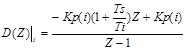
The design is made using the zero/pole-placement in the z-plane and with the “technical optimum” as a criterion all the processing and modulation delays have been taken into account. As such, the parameters are expressed in (13)
Where Ts is the sampling time. The filter capacitor Cf , previously neglected, only influences the current loops. In fact, the capacitor introduces zero and poles around the resonance frequency that do not modify the slow dc voltage loop. The d- and q-current loops are equivalent in the stability and dynamic analysis because once the compensations of the grid voltage
If the grid side current is sensed, the plant for control is
Where
G(z) being the zero order hold (ZOH) equivalent of G(s) and D(z) the controller usually designed on the basis of the “technical optimum.” In the following paragraphs, the stability and dynamic of the overall system are analyzed through the zeros and poles of the closed loop system in the z-plane and with the Bode plot [12].
5. Active damping of the current loops
The current controlled system can be made stable by changing the control algorithm, thus using so called “active damping.” In this case the active damping is obtained with a filter on the voltage reference for the modulator as shown in Fig. 5. The basic idea can be explained in the frequency domain by introducing a negative peak with the filter that compensates for the resonant peak due to the LCL-filter as shown in Fig.6. However, even if the solution seems simple, an optimization process for the choice of filter must be done in order to have the desired stability of the system and to preserve dynamics performance [11,12]. A GA is well suited to solve this optimization problem
Fig.5: Active damping using a filter on the voltage reference for the modulator
A. Genetic algorithm
The GA attempts to simulate Darwin’s theory on natural selection and Mendel’s work in genetics on inheritance: the stronger individuals are likely to survive in a competing environment. The GA uses a direct analogy of such a natural evolution. By evaluating many solutions of an assigned problem and combining them, the best one can be found. This method, also called derivative free optimization, does not need functional derivative information to search for a set of parameters that minimizes (or maximizes) a given objective function. Derivative freedom also relieves the requirement for differentiable functions, so an objective function can be used which, despite its complexity, avoids sacrificing too much computation time in extra coding. The GA considers the optimal solution of a problem as an individual [11], [21].

Fig. 6: Active damping action and the resulting transfer function of the stable system
The characteristics of the individual are due to the genes of his chromosomes in much the same way that the characteristics of a possible solution are due to its parameters. Thus, as the desired individual can be created through an evolutionary. Process starting from a random choice of individuals forming a population, the optimal solution can be found through a combination of a random set of solutions. In the following, the term “individual” indicates the possible solution, the term “gene” indicates one of the digits of the parameter of the solution and the “fitness value” indicates the degree of goodness of the individual [20-21]. The GA is both flexible and strong. Although it is a stochastic method, the fitness function and the encoding scheme give the search a solid and rational structure. Initialization of the GA is done by choosing the representation to be used and the size of the population. Subsequently, one needs to specify the crossover and mutation probabilities and a stop criterion [21]. The GA process is performed through the following iterative steps:
• Selection: the individuals are selected on the basis of their fitness value to reproduce in the mating pool;
• Crossover: each new individual is generated by two that are reproducing. This process is performed using part of the genes characterizing each individual;
• Mutation: the way to randomly produce new characters in the new individual of the population by changing one of its genes.
These genetic operations, if correctly implemented, can solve different kinds of problems.
B. Use of genetic algorithm for active damping optimization
A generic solution “i” of the problem is characterized by the following parameters: the coefficients
 (18)
(18)
The GA only needs a small amount of information from the overall system to solve, for example, stability problems or dynamic specification. This flexibility facilitates both structure and parameter identification in complex models such as the LCL-filter active rectifier. The active damping optimization algorithm is organized with a GA sub-routine for each coefficient
The first step is to decide on the desired position of the two pairs of complex-conjugate poles and how important it is for the algorithm to find a solution that minimizes the distance
Where,

Fig. 7: Algorithm used to search for optimum parameters of active damping on the basis of the genetic algorithm
Genetic operations of selection, crossover and mutation are used to produce the next generation of solutions suitable for the problem. The selection operation determines which individuals participate in producing the next generation. These members enter the mating pool with a selection probability proportional to their fitness values. After this step, a “two-point crossover” scheme is used. Crossover cannot reach the best solution if the population does not contain all the encoded information needed to solve the problem. Mutation allows other possible solutions to be generated and uniform mutation is adopted so that each bit has the same probability of mutation. This operation provides random excursions into new parts of the search space. There are many ways to terminate a GA, many of them similar to termination conditions used for conventional optimization algorithms [22], [23].
C. Using the genetic algorithm for active damping optimization
The individuals are generated randomly by the MATLAB algorithm “rand.” The elitism is then applied using the MATLAB algorithm “sort”: the vector composed by the fitness function a value of a generation is rearranged in such a way that the best fitness values are ranked last in the vector and they will not participate in crossover and mutation, i.e., they will continue to survive in the next generation. The individuals which are not part of the elite group will reproduce in the mating pool. The individuals have been encoded using the MATLAB “num2str.” In this way, each digit of the coefficient, representing a gene, is part of a string and it can be exchanged with another individual (crossover) or randomly changed (mutation). The “crossover” is implemented, randomly choosing where to cut each individual string. The string is divided into three parts and the “two point crossover” is adopted as the increase of the cutting points reduces the algorithm performance [10], [11].
The crossover is performed with a probability of 100% which means it is executed at every cycle. The “mutation” is implemented randomly changing. One gene on chromosome stands for one digit. The “mutation” is performed with a probability of 1%, otherwise the genetic algorithm could result in a random search. The number of individuals chosen for elitism is determined by the need to find the best solution with a reduced number of attempts. The elitism is chosen equal to 6 (30% of the population) and is a good trade-off between the need to find the best possible solution and the convergence of the genetic algorithm search. The relation between the two weights adopted for the cost function, one for the “dynamic” poles and the other for the “stability” poles, depends on which aim is considered more important. If the pole position indicated is reasonable. A good strategy in choosing reasonable aims is to individuate the passive damping needed to have the desired position of the high frequency poles and the proportional coefficient needed to have the desired bandwidth. Then the genetic algorithm tuning can be used to reach both the stability and dynamics of the overall system, thus finding a good trade-off oriented in a preferred direction with a small number of attempts in comparison with complex optimization algorithms that usually work well in the neighborhood of the initial state. Since the initial state is often unknown in the tuning of the active damping network and the number of constraints can differ from the number of coefficients to be optimized, the genetic algorithm can also guarantee a sensible reduction of the hours needed for the tuning [11].
6. Stability analysis
Usually the damping of the system is chosen in a qualitative manner, resulting in a decrease of efficiency and unknown dynamic of the system. Design guidelines for both passive and active damping are given and with different approaches. However, the possible variants in the system configuration, due to the position of the current sensors, presence of delays, tuning of the PI parameters and switching frequency are many. Thus passive and active damping have sometimes opposite effects in different systems. The un-damped system is always unstable if the current sensors are on the converter side, can be stable if the grid sensors are on the grid side. It is worth to highlight that these results as shown in Fig.8 (a) and (b) are strongly dependent on the parameters of the LCL filter. Thus it is very important to clearly fix the constraints both on the damping of the two high frequency poles and on the dynamic of the system (thus on the damping of the right plane poles). It is difficult to comply with them using a simple design method; thence it is very attractive to use soft computing optimizing methods such as genetic algorithm in shown in Fig.8 (a)&(b) [11].
7. Discussion on results
The LCL filter consists of an LC filter 3.5mH, and on the grid side, the transformer’s inductance as 2.7mH. The setup consists of:• Inverter/converter rated power: 1KVA
• Rated input LCL filter frequency: 50-60 Hz
• Rated output voltage: 3x230 V
• Rated output frequency:50-55Hz
• Rated output current: 4.6/4.8 A(max)
• 2 series connected Delta Electronica DC power supplies
• Type: SM300 D10
• Rated power: 3KW
• Rated current: 10A
• Rated voltage: 330V as shown in Fig.9, and result output waveform shown in Fig.10 to Fig.15.
Fig 8(a) shows in position of poles and zeros without optimization and fig 8(b) uses GA optimization method stable position of poles and zeros. Research project set-up in laboratory circuit diagram using inverter, microcontroller for PI controller using PWM modular, LCL filter with connected grid system in shown Fig.9.Using Psim software and design model of 3-Ø inverter using 8KHz PWM frequency and LCL filter though connected 3-Ø grid system shown in Fig.10 and Psim research model result o/p voltage, current LCL filter waveform and o/p grid voltage, current waveform system is stable some second shown in Fig.11. Using MATLAB software and design research model using value of different parameter in Fig.12 and o/p 3-Ø voltage, current waveform and filter waveform fuel cell waveform and after some second system will be stable shown in Fig.13. Now research model design and on line implement using this parameter and switching frequency shown wave form o/p inverter voltage and though LCL filter connected in 3-Ø grid in Fig.14 and Fig.15.
 starting population")
(a)
 final results")
(b)
Fig. 8: Closed loop current root locus with GA optimized active damping (a) starting population (b) final results

Fig. 9: Experimental set up

Fig. 10: Psim model

Fig. 11: Output waveforms of the Psim model shown in Fig. 10

Fig. 12: MATLAB proposed model

Fig. 13: Output Vo, Io & fuel cell
waveforms
(MATLAB results for the research)

Fig. 14: Output result waveform

Fig. 15: Output waveform with LCL-filter
Conclusions
This research work focuses on the design of the active damping for three-phase active rectifiers as a three-phase inverter using a genetic algorithm. It is not possible to define an ideal classic design method for active damping that could be valid for the position of the current sensors, the voltage sensors, the presence of delays, the tuning of the PI parameters and the sampling frequency. Thus the genetic algorithms are good solution to find the best parameters of the active damping methods. In particular, they have proved to be particularly suitable in reducing the susceptibility of the system in a high polluting environment. Moreover it is possible to define the desired bandwidth of the current control and the desired damping of the high frequency poles and make them have different weights in the GA-based optimization process. Genetic algorithms are used only for the optimum choice of the parameters of the active damping method using off-line application and it is not used in on-line implementation.References
[1] M. Liserre, A. Dell’Aquila, and F. Blaabjerg, ‘‘Stability improvements of an LCL filter based three-phase active rectifier,’’ Power Electronics Specialists Conference, 2002. PESC’02. IEEE 33rd Annual, Vol. 3, pp. 1195–1201, 23-27 June.
[2] Frede Blaabjerg, Remus Teodorescu, Zhe Chen, and Marco Liserre. “Power converters and control of renewable energy systems. In Proceedings of ICPE”, pages 2–20, 2004.
[3] Marco Liserre, Remus Teodorescu, and Frede Blaajerg. “Stability of photovoltaic and wind turbine grid-connected inverters for a large set of grid impedance values”. In IEEE TRANSACTIONS ON POWER ELECTRONICS, volume 21, January 2006- 2006.
[4] M. Malinowski, M.P. Kazmierkowski, W. Szczygiel, and S. Bernet. “Simple sensorless active damping solution for three-phase pwm rectifier with lcl filter”. In Industrial Electronics Society, IECON 2005. 31st Annual Conference of IEEE, page 5pp., 6-6 Nov.
[5] Remus Teodorescu and Frede Blaabjerg. "Flexible control of small wind turbines with grid failure detection operating in stand-alone and grid-connected mode”. In IEEE TRANSACTIONS ON POWER ELECTRONICS, volume 19, pages 1323–1332, 2004.
[6] P.A. Dahono. “A method to damp oscillations on the input LCL filter of current-type ac-dc pwm converters by using a virtual resistor. In Telecommunications Energy Conference”, 2003. INTELEC ’03. The 25th International, pages 757–761, 19-23 Oct. 2003.
[7] P.A. Dahono. “A control method to damp oscillation in the input LCL filter. In Power Electronics Specialists Conference”, pesc 02.june- 2002 IEEE 33rd Annual, volume 4, pages 1630–1635, 23-27.
[8] W. Gullvik, L. Norum, and R. Nilsen. “Active damping of resonance oscillations in lcl-filters based on virtual flux and virtual resistor”. In Power Electronics and Applications, 2007 European Conference on, pages 1–10, 2-5 Sept.
[9] Wessels, J. Dannehl, and F.W. Fuchs. “Active damping of LCL-filter resonance based on virtual resistor for pwm rectifiers &stability; analysis with different filter parameters”. In Power Electronics Specialists Conference, 2008. PESC 2008. IEEE, pages 3532–3538, 15-19 June.
[10] V. Kaura V. Blasko. “A novel control to actively damp resonance in input LCL- filter of a three-phase voltage source converter”. IEEE TRANSACTIONS ON INDUSTRY APPLICATIONS, 33:542–550, 1997.
[11] Frede Blaabjerg Marco Liserre, Antonio Dell’ Aquilla. “Genetic algorithm-based design of the active damping for an lcl-filter three-phase active rectifier”. IEEE TRANSACTIONS ON INDUSTRY APPLICATIONS, 19:76–86, January 2004.
[12] Mihai Ciobotaru. Reliable Grid Condition Detection and Control for “Single-Phase Distributed Power Generation Systems. PhD thesis”, Aalborg University, 2009.
[13] F. L. M. Antunes S. V. Araujo. “LcL filter design for grid-connected NPC inverters in offshore wind turbines”. The 7th International Conference in Power Electronics, 1:1133–1138, 22-26 October, 2007 / EXCO, Daegu, Korea.
[14] IEEE Std. 519-1992 - IEEE Recommended “Practices and Requirement for HarmonicControl in Electrical Power Systems” U IEEE Industry Applications Society/ Power Engg. Society., 1992.
[15] M. Liserre, F. Blaabjerg, and S. Hansen. “Design and control of an lcl-filter based three-phase active rectifier. In Industry Applications Conf.”, 2001. Thirty-Sixth IAS Annual Meeting. Conference Record of the 2001 IEEE, volume 1, pages 299– 307vol.1, 30 Sept.-4 Oct.
[16] Pasi Peltoniemi. “Comparison of the effect of output filters on total harmonic distotionn of line current in voltage source line converter - simulation study”.
[17] Alin Raducu. “Control of grid side inverter in a b2b configuration for wt applications”. Master’s thesis, Aalborg Universitet, 2008.
[18] A. Timbus, R. Teodorescu, F. Blaabjerg, and M. Liserre. “Synchronization methods for three phase distributed power generation systems. an overview and evaluation. In Power Electronics Specialists Conference”, 2005. PESC ’05. IEEE 36th, pages 2474–2481, 16-16 June 2005.
[19] M. Ciobotaru, R. Teodorescu, P. Rodriguez, A. Timbus, and F. Blaabjerg. “Online grid impedance estimation for single-phase grid-connected systems using pq variations”. In Power Electronics Specialists Conference, 2007. PESC 2007. IEEE, pages 2306–2312, 17-21 June 2007.
[20] D. H. Ackley.” A Connectionist Machine for Genetic” Hillclimbing. Kluwer Academic Publishers, Boston, MA, 1987.
[21] A. S. Austin. “Genetic solution to xor problems”. AI EXPERT, pages 52-57, December 1990.
[22] T. Back. Evolutionary Algorithms in Theory and Practice, Oxford press, New York, 1996.
[23] T. Back, F. Hoffmeister, and H.-P. Schwefel. “A survey of evolution strategies”. In R. K. Belew and L. B. Booker, editors, Proceedings of the Fourth International Conference on Genetic Algorithms and Their Applications, pages 2-9, San Mateo, CA, July 1991.
Cite this paper
APA
Aparnathi, R., & Dwivedi, V. V. (2013). LCL Filter for 3-Ø Stable Inverter Using Active Damping Method. Open Science Repository Engineering, Online(open-access), e70081934. doi:10.7392/Engineering.70081934
MLA
Aparnathi, Rajendra, and Ved Vyas Dwivedi. “LCL Filter for 3-Ø Stable Inverter Using Active Damping Method.” Open Science Repository Engineering Online.open-access (2013): e70081934. Web. 28 Feb. 2013.
Chicago
Aparnathi, Rajendra, and Ved Vyas Dwivedi. “LCL Filter for 3-Ø Stable Inverter Using Active Damping Method.” Open Science Repository Engineering Online, no. open-access (February 28, 2013): e70081934. http://www.open-science-repository.com/engineering-70081934.html.
Harvard
Aparnathi, R. & Dwivedi, V.V., 2013. LCL Filter for 3-Ø Stable Inverter Using Active Damping Method. Open Science Repository Engineering, Online(open-access), p.e70081934. Available at: http://www.open-science-repository.com/engineering-70081934.html.
Science
1. R. Aparnathi, V. V. Dwivedi, LCL Filter for 3-Ø Stable Inverter Using Active Damping Method, Open Science Repository Engineering Online, e70081934 (2013).
Nature
1. Aparnathi, R. & Dwivedi, V. V. LCL Filter for 3-Ø Stable Inverter Using Active Damping Method. Open Science Repository Engineering Online, e70081934 (2013).
doi
Research registered in the DOI resolution system as: 10.7392/Engineering.70081934.

This work is licensed under a Creative Commons Attribution 3.0 Unported License.
We are looking for partners to help us develop this open access project further. Write to [email protected].
"I may be wrong and you may be right, and by an effort we may get nearer to the truth." Karl Popper
Export to Mendeley
|
Click on this icon. You'll need to log in. |

|